Showing posts with label 944. Show all posts

18/10/2015

How To Troubleshoot Porsche 944 Headlight Problems - Part A

THE WHY

Back in 2011 I wrote this post on how to troubleshoot a problem with the headlight lifting motor on my 1984 Porsche 944. It's now 2015 and I've had 4 trouble-free years with no headlight problems until the other day when my headlights would go up but would not retract back down. I checked the relay and the headlight fuse (Fuse 1 on the Additional Fuse Board) which were fine and then the lifting mechanism which had no obvious signs of binding so I turned my attention to troubleshooting the rest of the electronics.

For future reference anyone following my two guides on headlight problem troubleshooting should follow Part A first here (at least until the end of Step 1) then follow Part B if needed.


THE TASK

You will need the following:

Multimeter (capable of checking DC voltage and circuit continuity)
Flat bladed screwdriver

I also recommend that anyone reads the headlight tutorial at Clark's Garage which explains the theory of operation and has been a key guide in helping me write this post


THE HOW TO

STEP 1
- MOLEX Connector Test

I started by checking the voltages on the 4 pins on the headlight motor MOLEX connector (top arrow shown below)
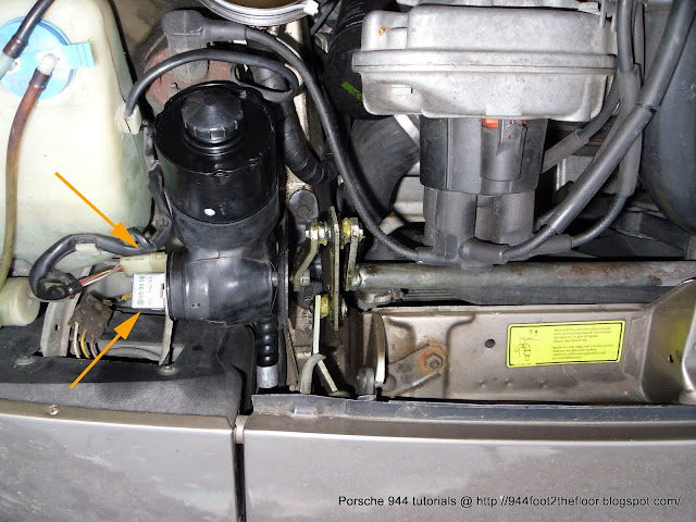


Start by disconnecting the connector from the motor housing and then test each pin individually with a multimeter (one probe of the multimeter should be attached to a good ground on the car, the second probe is used to test each pin individually - do not short the pins otherwise you will blow the headlight fuse under the dashboard).

Before checking the voltages at the connector it should be noted that the headlight switch has 3 position states which are as follows:

Position OFF: All lights should be OFF. Headlights in the DOWN retracted position
Position ON 1: Headlights should be OFF. Parking, dash and license plate lights should be ON
Position ON 2: Dash, parking, license plate and headlights ON. Headlights in the UP raised position

The MOLEX connector is wired in the following order (shown in the picture below)


To check the voltages at the MOLEX connector you need to perform the 3 following tests and the voltages on each individual pin should be near as follows:


Grey Red/Green Brown Red/Blue
TEST 1
Ignition OFF
Headlight switch OFF
0v 12v 0v 12v
TEST 2
Ignition ON
Headlight switch OFF
0v 12v 0v 12v
TEST 3
Ignition ON
Headlight switch ON position 2.
12v 0v 0v 12v


If you find that all the voltages are CORRECT then the problem is likely to be the headlight motor relay, the headlight lifting motor or binding of the headlight lifting mechanism. You should then follow tutorial Part B instead.

If you find that any voltages are INCORRECT (mine failed Test 1 and was only showing 4v on the Red/Green pin) then the problem is likely to be with headlight switch, headlight fuse or wiring. You should proceed to Step 2 below.


STEP 2 - Headlight Switch Connector and Fuse Board tests

If the voltages are INCORRECT at the MOLEX connector we need to follow the problem along the wire to the next point in the connection chain using the Porsche headlight electric diagram shown below (taken from Clark's Garage tutorial).


If we start at the area around the rotary switch (this is near enough the same area as the MOLEX connector) we can see the four coloured wires labelled.

  • Grey goes to the headlight switch  - Follow Step 2a
  • Red/Green goes to the headlight switch - Follow Step 2a
  • Red/Blue goes to the fuse board (Fuse 1 on the Additional Fuse Board) - Follow Step 2b
  • Brown goes to ground (bottom right) - You should do a continuity test between the pin on MOLEX connector and the ground point underneath the right front headlight, regardless you should unbolt and clean the ground point

STEP 2a - For the back of the headlight switch connector (Red/Green and Grey wires only)

Use a flat bladed screwdriver to pop the plastic headlight switch housing and remove it from the dashboard. Keep the headlight switch connected to the connector block and perform Test's 1, 2 & 3 on the back of the headlight switch connector for the Red/Green and Grey wires only (shown in the bunch below)


CORRECT voltages for the Red/Green or Grey wires indicate that the issue is likely the Red/Green or Grey wire itself (broken, shorting or poorly crimped at the connection points at either end), therefore the wire needs to be fixed or changed. In my case I was seeing 12v on the Red/Green wire on the back of the headlight switch connector, therefore my problem was the Red/Green wire itself as it was only 4v at the MOLEX end. There was no problem with the crimping at either end so I cut the wire at both ends and patched in a new length as it was too difficult to find a short or break. My headlights now retracted correctly.

INCORRECT voltages for the Red/Green or Grey wires indicate that the problem is likely a headlight switch fault or a problem with the main power wire to the switch. Therefore you need to do a switch continuity test (see Step 3) or a voltage test to the headlight switch connector block (see Step 4).


STEP 2b - For the fuse board (Red/Blue wire only)

Locate the 'Additional Fuse Board' underneath the dash (shown below), then locate Fuse 1 (16A) shown below.


There are two screws that hold the entire fuse board bracket to the underside of the dash, undo these so you can gain access to the back of Fuse 1. On the back of Fuse 1 you will see a Red/Blue wire and Red wire. 

CORRECT voltage for the Red/Blue wire indicates that the issue is the Red/Blue wire itself (broken, shorting or poorly crimped at the connection points at either end)

INCORRECT voltage for the Red/Blue wire indicates that the issue is a faulty fuse or that the fuse board is not receiving enough power. Recommend to replace 16A fuse and check Red wire on Fuse 1 is showing 12v


STEP 3 - Headlight Switch Continuity Test

This is what the inside of a brand new headlight switch looks like on a 944/1. The left-hand-side shows the dimmer variable resistor and the contact plates that connect to the various blade connectors on the back of the switch. The right-hand-side shows the 3 sprung switch plates that are activated/deactivated at the various 3 positions when the switch is cycled.


Here's what the inside of my used headlight switch looked like. The switch still functioned correctly but there was definitely signs of wear on the contact plates, so I replaced it just as a matter of caution.


To test the proper functioning of the switch remove the switch from car and do a continuity test using the various connector blades on the back (as shown below).


Using the below diagram you should get continuity at the red and green groups of points when the switch is in the various OFF and ON positions. If you fail to get these results you may be able to disassemble the switch and clean the contact points inside to get it working correctly. If all fails you will need to buy a new switch.

You can also test the resistance range between the 2 pins 58a and 59b for the dimmer. My new switch showed a range of between 0.5 to 7.0 ohms (Ω).


STEP 4 - Headlight Switch Connector Block Voltage Test

Testing the front of the headlight switch connector block is straight-forward and the correct voltages should be present using the table below.


Ignition OFF Ignition ON
X 0v 12v
56 0v 0v
58L 0v 0v
56K 0v 0v
58 0v 0v
30b 0v 0v
58R 0v 0v
30 12v 12v
58a 0v 0v
58b 0v 0v


Whilst the switch is detached from the block this is also a good opportunity to replace the bulb that illuminates the headlight switch. Bulb specs are as follows and can be found on ebay.

Osram 286 Single Bulb 12V 1.2W Dashboard Dash Interior Auxillary Car Single
Product Dimensions (mm): H 18 x W 5 x D 5
12v 1.2w W2 x 4.6d Indicator & Panel


22/07/2011

How To Replace The Front Stabiliser Bar Bushes On A Porsche 944 (Square Dash Model)

THE WHY

Having been trying to solve a previous problem (power steering oil cooler location) some months ago via the Pelican Parts forums a member pointed out to me that from the photos I'd posted he could see that one of the bushes on the front stabilisation bar looked like it needed replacing. I'd always thought it had seen better days but since the car had passed two previous MOT's I didn't think it was that serious. Anyhow having finally cleared the list of jobs on my 944 that I considered to have higher priority I thought I go back and investigate this one.

THE TASK


You will need the following tools:

13mm Ring Spanner
13mm Socket
10mm Socket
Socket Extension Bar
Socket Ratchet Spanner
A bench vice (optional)
1600mm G-Clamp or bigger (optional)
Washing-up Liquid

THE HOW TO


(Amateur mechanic job time approx. 2 hours)

Undo the 7 x 10mm bolts that secure the engine undertray to the vehicle and remove. You will then see the stabilisation bar running the width of the vehicle secured at either end to the front wishbones and to two supports (circled in orange below) that hang down from the engine bay walls.


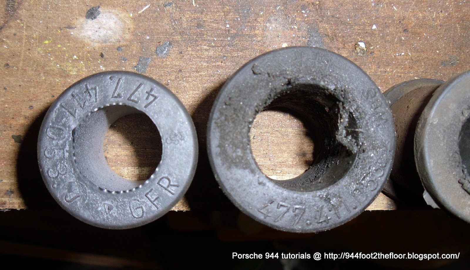
Before you can begin removing the stabilisation bar you need to start by either measuring the diameter of the stabilisation bar (at the points above circled in orange) or by cleaning enough grease and grime off one (or both) of the centre rubber bushes to reveal the Posche product code stamped on their edge. This is because for some unbeknown reason Porsche decided to make 3 different thickness (20mm, 21.5mm & 23mm) stabilisation bars. You then need to select the right size bushings for your bar. Mine happened to be the 23mm variety (Product code 477 411 053 J) of which I ordered two. The bushes at end of the stabilisation bar are the same diameter no matter what stabilisation bar you have, I ordered two of those too (Product code 171 411 314 A).

Here's a useful diagram and part numbers
Once you've sourced your bushes the next part involves undoing the 13mm nuts that hold the clips to the inner brackets (two per bracket) and then the 13mm nuts that secure the bearing brackets (two per bracket) to the wishbones.


I had very little trouble undoing the bolts on the inner brackets however when it came to one side of the bearings brackets at the wishbone I had to cut the bearing bracket off the wishbone with a grinder. Because the bearing brackets are only made from a light alloy it appeared some corrosion had gone on and because the bolt head is inset into the bracket this just chewed its way into the alloy and left me with a spinning nut.

With the stabilisation bar now removed I was able to easily pull off the bushes from either end. However the centre ones required a little bit of invention to pry open the clips for which I used the outer edge of some vice jaws and then wound out the vice as shown below.


With the clips removed the old rubber bushes simply slid off the bar. Here's a few photos comparing the old ones (centre) to the new ones (either end).


As you can clearly see the left centre bush has seen much better days. Its not surprising that it was in much worse shape than the other side as it sits on the side of the car that tends to get the worst of the oil leaks (power steering bottle, engine gasket and seal leaks).

With the bushes removed it was time to clean the stabilisation bar with some degreaser. This revealed some pitting that had occurred on the side of the worst bush.


Not wanting this to cut into the new bushes and neither wanting to purchase a new stabilisation bar I decided to smooth it off with a fine grindstone and emery paper to remove the worst of the pits.


The new centre bushes were then slid onto the bar with the aid of some washing-up liquid. And the clips were then slid over them and clamped in the vice so they were loosely secured around the bushes.

Because previously I had had to destroy one of the bearing brackets to get the bar off I ordered a complete new pair.


And the bushes to go in them.


The bushes are quite difficult to press into the bearing brackets. I found it was best to insert the top rounded edge in at an angle and then press in the sides. I obviously used washing-up liquid again and a little help from the vice being careful not to damage the rubber or alloy brackets as I pressed then right in.

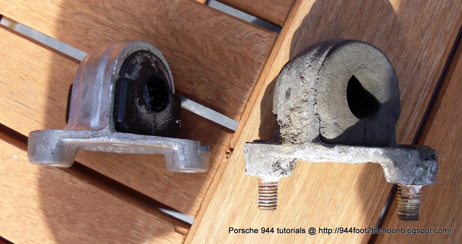
The bushes have obviously been modified since the ones that were previously on the car. Here's a photo showing the new vs the old.


As you can see from the photo above the old (good) bracket that I didn't have to cut off is pretty badly corroded, so much so that I couldn't even extract the bolts from it.

The next step involved pressing the bearing brackets and their new bushings onto either end of the bar. Again I had to improvise and found that clamping the curved part of the bar in the vice and then using a G-clamp to gradually wind and push down the bush onto the bar - again with help of some fairy liquid. This is not shown in the photo but I used a small plastic disc to stop the round G-clamp jaw from damaging the rubber bush as I would it on. This was by far the most difficult part of the job.


The final part involves re-fixing the bar to the car. I started by loosely clamping up the centre bush clips to the drop down brackets and then located the bolts through the outer bearing bracket bushes and into the holes in the wishbones. Everything was then tightened up and the engine pan put back on.

24/06/2011

Porsche 944 Camshaft Gasket Replacement Procedure

THE WHY

The trouble with fluid leaks is that it often takes some work deducing what fluid is leaking (water, engine oil, brake fluid, power steering fluid - to name a few) and where it is coming from. Having previously cured and therefore eliminated two fluid leaks on my 944 (power steering reservoir bottle and one from the OPRV Oil Pressure Relief Valve area) I was determined to get to the bottom of the next one. In this particular case unlike the previous fluid leaks (somewhere above the removable engine floor pan) this one was clearly coming from the rear of the engine and making its way down the back of the grilled engine sump. Being the middle of the week I thought I'd make a post on the Pelican Parts forums to see if anyone had some ideas as to where I should be looking. The response was fantastic.

THE TASK

10mm Socket
Small/Medium Socket Ratchet
Small/Medium Torque Wrench
Multi-purpose engine grease
800 Grit Emery Paper
Degreaser
Camshaft Gasket ( Part No. 9281058902 )

THE HOW TO

(Amateur mechanic job time approx: 1-2 hours)

Here's the picture I posted to the Pelican Parts forums, you can see the dark oily trail down the back of the grilled sump.


As I said earlier the response by the board members was fantastic and if you read the post it seemed pretty clear the oil was coming from one or more of four possible places.

The possibilities were:

A.) The cam gasket housing
B.) The lower balance shaft plug o-ring
C.) Balance shaft housing to block sealant
D.) Oil pan gasket

Judging by the discussion, possibility 'A' was the first thing to check after having taken photos of all the surrounding areas. Apparently the gasket is made of cork and doesn't have particularly long lifespan. Here's a picture to show the culprit area.


The cam gasket sits between the cover and the main head block at the back of the engine bay (circles below).


The easiest way to check if it is leaking is to get you fingers under the lowest edge of the cap and check for oily matter running down the back of the block. If like me you find some then wipe it dry and then give the car a good drive before you check again. If the oil has returned you know the gasket needs replacing.

As per a suggestion on the forum I followed the description on Clarks Garage (right at the bottom of the article titled "Rear Cam Housing Gasket Replacement)

Removal of the cam gasket and cap is fairly straight forward and involves undoing 3 x 10mm bolts, the lowest one is a bit difficult to get to so you will probably need a small 10mm socket and ratchet. With the three bolts undone and a little wiggle the cam cap and attached engine hoist loop will come off in your hands.

As you can see from the following two pictures there is a clear amount of oil present on the lower edge of both the engine hoist loop and cam cap cover.

(Engine Hoist Loop)


(Cam cap cover)


Now turning the cap over shows the charcoal-like remains of the cork gasket itself


Without scratching the metal surface of the cap try to remove the old pieces of gasket with a blunt object like a plastic scraper or bicycle tyre lever.


Next I cleaned up the cap with some degreaser and then laid down some fine 800 grit emery paper on a flat surface and lightly rubbed the flat mating surface of the cap to remove any fine pieces of gasket and dirt.

Here's a picture of the new OEM gasket from Porsche.


And here it is alongside the cleaned-up cap


Now take a small amount of engine grease and lightly coat one side of the gasket before aligning it on top of the cap. This helps create a good seal as well as aiding the re-installation procedure.


Next I cleaned up the surface of the engine block with some blue tissue paper making sure there was no old bits of gasket, oil or dirt.


Before installing the cap make sure you apply some more grease to side that will pressing against the block as well as remembering to attach the engine hoist loop. Do all three 10mm bolts up to finger tightness and then STOP.

This bit is very very important. The bolts must be correctly tightened using a torque wrench to 8 Nm (6 ft-lb). This is very important to make sure the cap seals evenly all round. Again I would suggest you get yourself a small/medium sized torque wrench as the bottom 10mm bolt is very awkward to get to.

And finally a picture to show the finished result.

22/06/2011

How To Remove And Replace Porsche 944 Transmission Drive Axle Seals

THE WHY

If you're experiencing an oil leak coming from the rear of your Porsche 944 then it is probably coming from the transmission/gearbox's oil filling plugs (there are two) or more likely one/both of the drive axle seals (one either side where the drive axle meets the transmission). Other symptoms include harder than usual shifting or transmission whine due to lack of transmission oil. Having replaced the filling plugs for new ones at the last gearbox oil change it was pretty easy to trace the black greasy patch on the underside of the transmission to both the drive axle oil seals - they simply needed replacing.

THE TASK

I used the following:

8mm Spline Bit
8mm Hex Socket
17mm Hex Socket
Socket Ratchet Spanner
Torque Wrench
Socket Extension Bar
Small/Medium Heel Pry Bar or Seal Puller Tool
Seal Press or 38-40mm socket
Rubber Mallet
2 x Radial Shaft Seals (Porsche OEM Part number 016 409 399 B)
1 x Large Zip Tie or Length Of String/Rope
Spray Degreaser
Oil Drain Pan.
Stiff Scrubbing Brush
Axle Stands
Trolley Jack
Swepco 201 Gear Oil
Anti-seize thread lubricant
White Spirit
Karcher Powerwasher (optional)


THE HOW TO


(Amateur mechanic job time approx: 2-3 hours).

Start by raising the rear of the car and support on axle stands (the higher you can get the rear off the floor the easier the job becomes). As you can see from the photos below the seals on mine were leaking quite badly from both sides.


Depending how badly the seals have been leaking now might be the time to give the transmission underside a blast with the powerwasher and degreaser. The purpose of this is it makes the job a lot less messy and enables you to check for leaks once the job is complete.

Now follow my tutorial on how to remove the transmission oil, you will also need to refer to this when it comes to refilling the transmission once you've replaced the seals.

With the oil drained it's now time to remove drive axles where they meet the transmission. Start with the one that isn't under the exhaust (shown below) as it is the easier of the two and is a good way of getting a clear idea of what needs to be done when you start the slightly obstructed exhaust side.


To release the drive axle you need to undo 8 x 8mm spline screws. Make sure the spline bit goes in straight and not at an angle otherwise you risk rounding off the spline bit and probably the screw too. If you find it difficult to get a good angle on some of them then simply release the handbrake and rotate the wheel to improve the access.

With the spline screws removed you should now be able to move one end of the axle. Find a suitable place to hang the drive axle out of the way and cover the end with a plastic bag (this stops any grit getting stuck to grease in the universal joint).

The next step involves removing the flanged shaft. Start by poking an old screwdriver all the way through one of the empty spline screw holes, this stops the flange from moving when you release the 8mm hex screw from it's centre. Use a socket wrench with extension bar and 8mm hex bit to undo the centre screw as shown below.


Once the screw is removed the flanged axle should simply slide out. Give it a good clean and check there's no wear or rough areas on the axle near the flanged end.


Now we can see the large black coloured seal we are going to remove. I used a small heeled pry bar (or you can use a seal puller or other hooked instrument) to gently work around the seal and ease it out. Be careful when doing so as the blind side of the seal that you can't see contains and elasticated spring and it's easy to leave this behind in the transmission. Keep at it and the seal will eventually come out.

(Seal before removal)


(Blind-side of seal and elasticated spring)


(Seal removed)


Once removed it's a good idea to thoroughly clean the area so that no grit or muck enters the transmission when you come to install the new seal.

Here you can see the new seal (left) alongside the old seal (right)


You are now ready to install the new seal. Before you do so, take note of the small raised lip (see arrow below) that the new seal must press up against inside the seal hole. Now take a small amount of white spirit and lightly rub some of it around the outer edge of the black seal (this aids fitting and will shortly evaporate). Now press the seal squarely into the hole making sure the spring is facing in towards the transmissions internals. Now take a 38-40mm socket and a rubber mallet and gently tap the seal into place making sure it doesn't skew as you knock it in. Use your fingers every now and again to feel around the inside of the seal to see when it is fully pressed up against the lip on the inside.

Photo below shows a 38mm socket compared to the size of the seal.


And photo below shows the seal correctly fitted.


Now you can re-install the flanged axle and re-attach the drive axle shaft. You may also want to take this opportunity to refresh the grease in the CV joint at the end of the drive axle before reattachment.

Now all that remains is to repeat the procedure for the other side before refilling the transmission gear oil.