THE WHY
My 944 usually only sees action at the weekends and most weeks sits patiently in its parking spot on my road. I remember it had been a particularly wet week and one morning when I left the house I glimpsed an unexpected amount of oil floating on the surface of the water that was laying in the kerb by the side of my car. That evening I had to do a short drive and instantly it became clear that things with the steering were not at all well. As soon as I turned out of my road a resonating groan came from the direction of the engine and was repeated at nearly every other turn until I reached my destination. A quick check in the power steering bottle confirmed it was almost empty and nowhere near as full as it should have been. At first I suspected that a power steering line that had been badly fitted by a previous owner (it was on my list of things to do) was the culprit. However when I had a look in the clear light of day it was coming from completely the opposite side. Having quickly whipped off the undertray it was clear the leak was coming from the rubber bellow at the end of the steering rack.
THE TASK
You will need the following:
32mm Spanner
32mm Socket (optional)
19mm Socket and/or ring spanner
17mm Socket and/or ring spanner
2 x 13mm Socket and/or ring spanner
2 x 10mm Socket and/or ring spanner
Flat bladed screwdriver
Centre Punch (optional)
Small hammer
ATF (Automatic Transmission Fluid) Dexron II
General purpose grease
WD-40 or similar penetrating oil
Oil catch tray
THE HOW TO
(Amateur mechanic job time approx. 2-3 hours)
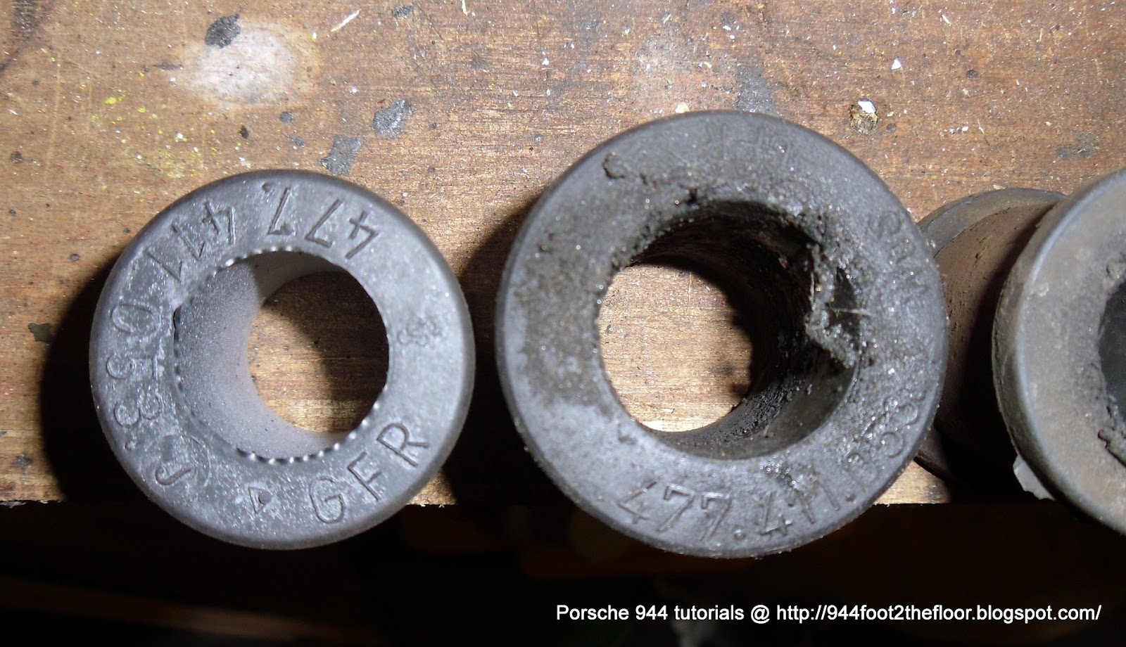
It is worth pointing out straight away that the power steering rack for right and left-hand drive cars are identical, however the suspension cross-member and the way the power steering rack attaches to the cross-member are different.
Left-hand drive cars have two extra mounting adapters that secure the rack to the crossmember (as shown in the Porsche parts picture below) whereas right-hand drive cars don't, the rack simply bolts straight to the crossmember and no adapters are needed.
Left-hand drive power steering rack (Red arrows show adapter brackets)

Left-hand drive cross member (mounts at 90 degrees on front, no hole for steering gearbox)


Right-hand drive power steering rack (without adapters)

Right-hand drive cross-members (blue arrows show mounts at 45 degrees on front and orange arrow shows hole for steering gearbox)


To make this job as easy as possible raise the front of car as high as you can go, then remove the undertray by undoing the 5 bolts that hold it on. If you are doing this on your own it also helps to remove the front wheels to take the weight off the track rods when you detach them from the rack.
Next step is to confirm you actually that leak is coming from the rack itself, if it is then nine times out of ten you'll see red fluid coming from one or both of the black rubber gators as was the case with one of mine.
Pop the gator off at the end that is attached to the rack and roll it back to expose the 32mm nut that attaches the steering track rod to the rack inside. On the edge of the nut you should notice it has notch that has been tapped; this is to prevent the nut from undoing, thus before you can undo the nut you need to tap back this notch so that it will pass the groove it sits in.

With the nut undone position the track rod so it is not in your way and repeat the procedure for the other side.

Next position an oil catch tray underneath the car and detach the hose at the point where it connects to the power steering coiled oil cooler (shown by blue arrows below) and drain as much power steering fluid as you can. It helps to undo the cap on the power steering bottle so a vacuum isn't created.

With most of the oil drained you can now detach the other hose from the point where it meets the power steering pump (blue arrow below) with a 19mm spanner/socket and catch the remaining oil.

With the hoses removed you are now almost ready to begin detaching the rack itself. At this point if you are following the Haynes or Porsche 944 workshop manual it will tell you to remove the stabiliser bar, this may be necessary for left-hand drive cars but I was able to manoeuvre/wiggle the rack about and remove it on my right-hand drive 944 without doing this and it wasn't too much hassle.
To remove the rack start by undoing the four 13mm bolts that secure it to the cross-member.

Don't undo the bolts completely though as you also need to undo and remove the single 13mm bolt (blue arrow below) that attaches the steering linkage to the rack. Keeping the rack momentarily held by the four steering rack mounting bolts aids its removal. It helps to spray some penetrating oil on the bolt and spline itself as it can be difficult to undo and ease apart. You must remove the bolt completely as there is a grove in the spline that it sits in. With the bolt removed if the linkage won't budge off the spline you can tap a screwdriver into the slot and ease the jaws of the clamp slightly, use more penetrating oil if you have to.

With the linkage detached and the four cross-member bolts now completely removed you can proceed to wiggle/twist and manoeuvre the rack free from the car.

The only thing left for me to do was detach the two steering oil lines from the rack that I had detached from the pump and oil cooler earlier (the large thick one in the picture above and the skinnier one shown by itself in the picture below). You will use these again with new copper washers on the replacement rack.

The replacement rack was a reconditioned part with all new seals and brand new rubber gators that I got from a seller on ebay who specialises in replacement steering racks for all types of cars. The rack arrived within a day or so as a complete unit (you have to send him back the old rack as part of the deal). I also purchased some replacement copper washers for where the steering oil lines attach to the rack and steering pump, I got these from a general auto store for few pennies.
As a side note if you are interested in replacing the seals on the rack yourself check out the tutorial here on Rennbay http://www.rennbay.com/psrsealkitfull.html
You will now need to reconnect the lines to rack with the new copper washers (following the correct torque settings in the Porsche manual).
Next step is manoeuvre the new rack back into position on the car. Use 2 of the 4 mounting bolts to loosely hold it in place whilst you line up steering linkage with the spline (make sure the flat groove on the spline lines up with the bolt hole otherwise the bolt will not tap through). When the linkage is attached you should be able to see clear through the bolt hole and the bolt should just push/tap through with ease. If you're slightly out of alignement even by 1 or 2 notches on the spline the bolt will not got through and you'll need to repeat the whole alignment procedure again. It took me 2-3 attempts to get this right.
Don't worry at this point trying to centre the tracking with the steering wheel in the car as you will do this at the very end when the wheels are back on the car. This is a simply case of pointing the wheels directly ahead and removing and adjusting the steering wheel.
With the linkage attached and bolted to the spline you can do up all four steering rack mounting bolts so the rack is now securely in place.
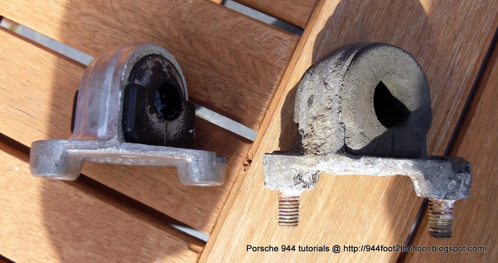
The next step is to fit the new gators to the track rods. I found the easiest method was first to use a little grease around the openings of the gators and slide a 32mm socket inside side them first.

This helps you easily slide the gators over the wobbly joint on the end of the track rod (you can just see the socket butted up against the wobbly joint pointed out by the orange arrow below)


Slide the gator all the way onto the track rod and onto the rubber bung (shown top left in the photo above).
You are now ready to hook the track rods back up to the rack. Carefully line up the threads on each side and do up the wobbly joints so they are finger tight. Then tighten them with a spanner. It is important that you use a punch or flat bladed screwdriver to tap the locking notch back into place (as shown below by the orange arrow). This prevents your steering coming apart through vibration and is an essential safety feature.

The final step involves putting a light amount of general purpose grease on the steering rack itself before the rubber gators are attached to either end of the rack.
You are now ready to reattach the hoses from the rack to power steering pump and pipe from the power steering oil cooler.

As a precaution I used some plastic cable protector to wrap the pipe to prevent it rubbing on some points on the chassis (shown by orange arrows below).

With all the pipes connected (making sure they are routed correctly and away from any belts or other moving parts, plus clean any old ATF fluid away from any of the pipe joints as this makes it easy to identify new leaks as opposed to phantom ones) you are now ready to fill up the power steering bottle to the level on the dip-stick. Pour in the ATF fluid as slowly as you can as you want to minimise creating bubbles. When the level appears to to remain constant and with the car still raised off the ground start the ignition and allow the engine to run. Keep checking the level in the power steering bottle and top up as necessary. When the level appears to remain static slowly turn the steering wheel completely to the left, top up power steering fluid. Then turn the steering wheel completely to the right, top up power steering fluid. Repeat several times until no change in the fluid level occurs. Turn off the ignition and slide back under the car to check for leaks at all the points where you disconnected/re-connected the power steering hoses, if no red fluid appears to be leaking from anywhere and the fluid level hasn't dropped then it looks like you have done a good job. Before re-attaching the under-tray I took the car for a quick test run, brought it back, checked for leaks and did a small top-up on the fluid and that was that.
If you find that your steering wheel is not centered then make sure the road wheels are facing forward as straight as you can get them by manoeuvring the car. Then pull off the horn button that sits across the centre of the steering wheel. Use a socket with and extension bar to undo the big nut in the centre. Then simply pull off the steering wheel, adjust it to the correct position, reattach the nut and horn button and you are done.
As a final bonus and if your power steering pump needs an overhaul you can find a good tutorial for it below.
My 944 usually only sees action at the weekends and most weeks sits patiently in its parking spot on my road. I remember it had been a particularly wet week and one morning when I left the house I glimpsed an unexpected amount of oil floating on the surface of the water that was laying in the kerb by the side of my car. That evening I had to do a short drive and instantly it became clear that things with the steering were not at all well. As soon as I turned out of my road a resonating groan came from the direction of the engine and was repeated at nearly every other turn until I reached my destination. A quick check in the power steering bottle confirmed it was almost empty and nowhere near as full as it should have been. At first I suspected that a power steering line that had been badly fitted by a previous owner (it was on my list of things to do) was the culprit. However when I had a look in the clear light of day it was coming from completely the opposite side. Having quickly whipped off the undertray it was clear the leak was coming from the rubber bellow at the end of the steering rack.
THE TASK
You will need the following:
32mm Spanner
32mm Socket (optional)
19mm Socket and/or ring spanner
17mm Socket and/or ring spanner
2 x 13mm Socket and/or ring spanner
2 x 10mm Socket and/or ring spanner
Flat bladed screwdriver
Centre Punch (optional)
Small hammer
ATF (Automatic Transmission Fluid) Dexron II
General purpose grease
WD-40 or similar penetrating oil
Oil catch tray
THE HOW TO
(Amateur mechanic job time approx. 2-3 hours)
It is worth pointing out straight away that the power steering rack for right and left-hand drive cars are identical, however the suspension cross-member and the way the power steering rack attaches to the cross-member are different.
Left-hand drive cars have two extra mounting adapters that secure the rack to the crossmember (as shown in the Porsche parts picture below) whereas right-hand drive cars don't, the rack simply bolts straight to the crossmember and no adapters are needed.
Left-hand drive power steering rack (Red arrows show adapter brackets)

Left-hand drive cross member (mounts at 90 degrees on front, no hole for steering gearbox)


Right-hand drive power steering rack (without adapters)

Right-hand drive cross-members (blue arrows show mounts at 45 degrees on front and orange arrow shows hole for steering gearbox)


To make this job as easy as possible raise the front of car as high as you can go, then remove the undertray by undoing the 5 bolts that hold it on. If you are doing this on your own it also helps to remove the front wheels to take the weight off the track rods when you detach them from the rack.
Next step is to confirm you actually that leak is coming from the rack itself, if it is then nine times out of ten you'll see red fluid coming from one or both of the black rubber gators as was the case with one of mine.
Pop the gator off at the end that is attached to the rack and roll it back to expose the 32mm nut that attaches the steering track rod to the rack inside. On the edge of the nut you should notice it has notch that has been tapped; this is to prevent the nut from undoing, thus before you can undo the nut you need to tap back this notch so that it will pass the groove it sits in.

With the nut undone position the track rod so it is not in your way and repeat the procedure for the other side.

Next position an oil catch tray underneath the car and detach the hose at the point where it connects to the power steering coiled oil cooler (shown by blue arrows below) and drain as much power steering fluid as you can. It helps to undo the cap on the power steering bottle so a vacuum isn't created.

With most of the oil drained you can now detach the other hose from the point where it meets the power steering pump (blue arrow below) with a 19mm spanner/socket and catch the remaining oil.

With the hoses removed you are now almost ready to begin detaching the rack itself. At this point if you are following the Haynes or Porsche 944 workshop manual it will tell you to remove the stabiliser bar, this may be necessary for left-hand drive cars but I was able to manoeuvre/wiggle the rack about and remove it on my right-hand drive 944 without doing this and it wasn't too much hassle.
To remove the rack start by undoing the four 13mm bolts that secure it to the cross-member.

Don't undo the bolts completely though as you also need to undo and remove the single 13mm bolt (blue arrow below) that attaches the steering linkage to the rack. Keeping the rack momentarily held by the four steering rack mounting bolts aids its removal. It helps to spray some penetrating oil on the bolt and spline itself as it can be difficult to undo and ease apart. You must remove the bolt completely as there is a grove in the spline that it sits in. With the bolt removed if the linkage won't budge off the spline you can tap a screwdriver into the slot and ease the jaws of the clamp slightly, use more penetrating oil if you have to.

With the linkage detached and the four cross-member bolts now completely removed you can proceed to wiggle/twist and manoeuvre the rack free from the car.

The only thing left for me to do was detach the two steering oil lines from the rack that I had detached from the pump and oil cooler earlier (the large thick one in the picture above and the skinnier one shown by itself in the picture below). You will use these again with new copper washers on the replacement rack.

The replacement rack was a reconditioned part with all new seals and brand new rubber gators that I got from a seller on ebay who specialises in replacement steering racks for all types of cars. The rack arrived within a day or so as a complete unit (you have to send him back the old rack as part of the deal). I also purchased some replacement copper washers for where the steering oil lines attach to the rack and steering pump, I got these from a general auto store for few pennies.
As a side note if you are interested in replacing the seals on the rack yourself check out the tutorial here on Rennbay http://www.rennbay.com/psrsealkitfull.html
You will now need to reconnect the lines to rack with the new copper washers (following the correct torque settings in the Porsche manual).
Next step is manoeuvre the new rack back into position on the car. Use 2 of the 4 mounting bolts to loosely hold it in place whilst you line up steering linkage with the spline (make sure the flat groove on the spline lines up with the bolt hole otherwise the bolt will not tap through). When the linkage is attached you should be able to see clear through the bolt hole and the bolt should just push/tap through with ease. If you're slightly out of alignement even by 1 or 2 notches on the spline the bolt will not got through and you'll need to repeat the whole alignment procedure again. It took me 2-3 attempts to get this right.
Don't worry at this point trying to centre the tracking with the steering wheel in the car as you will do this at the very end when the wheels are back on the car. This is a simply case of pointing the wheels directly ahead and removing and adjusting the steering wheel.
With the linkage attached and bolted to the spline you can do up all four steering rack mounting bolts so the rack is now securely in place.
The next step is to fit the new gators to the track rods. I found the easiest method was first to use a little grease around the openings of the gators and slide a 32mm socket inside side them first.

This helps you easily slide the gators over the wobbly joint on the end of the track rod (you can just see the socket butted up against the wobbly joint pointed out by the orange arrow below)


You are now ready to hook the track rods back up to the rack. Carefully line up the threads on each side and do up the wobbly joints so they are finger tight. Then tighten them with a spanner. It is important that you use a punch or flat bladed screwdriver to tap the locking notch back into place (as shown below by the orange arrow). This prevents your steering coming apart through vibration and is an essential safety feature.

The final step involves putting a light amount of general purpose grease on the steering rack itself before the rubber gators are attached to either end of the rack.
You are now ready to reattach the hoses from the rack to power steering pump and pipe from the power steering oil cooler.

As a precaution I used some plastic cable protector to wrap the pipe to prevent it rubbing on some points on the chassis (shown by orange arrows below).

With all the pipes connected (making sure they are routed correctly and away from any belts or other moving parts, plus clean any old ATF fluid away from any of the pipe joints as this makes it easy to identify new leaks as opposed to phantom ones) you are now ready to fill up the power steering bottle to the level on the dip-stick. Pour in the ATF fluid as slowly as you can as you want to minimise creating bubbles. When the level appears to to remain constant and with the car still raised off the ground start the ignition and allow the engine to run. Keep checking the level in the power steering bottle and top up as necessary. When the level appears to remain static slowly turn the steering wheel completely to the left, top up power steering fluid. Then turn the steering wheel completely to the right, top up power steering fluid. Repeat several times until no change in the fluid level occurs. Turn off the ignition and slide back under the car to check for leaks at all the points where you disconnected/re-connected the power steering hoses, if no red fluid appears to be leaking from anywhere and the fluid level hasn't dropped then it looks like you have done a good job. Before re-attaching the under-tray I took the car for a quick test run, brought it back, checked for leaks and did a small top-up on the fluid and that was that.
If you find that your steering wheel is not centered then make sure the road wheels are facing forward as straight as you can get them by manoeuvring the car. Then pull off the horn button that sits across the centre of the steering wheel. Use a socket with and extension bar to undo the big nut in the centre. Then simply pull off the steering wheel, adjust it to the correct position, reattach the nut and horn button and you are done.
As a final bonus and if your power steering pump needs an overhaul you can find a good tutorial for it below.
Also, here's an overview of the power steering system on a left-hand drive 944 you may find useful too.
--- UPDATE June 2022 ---
So, it's been 11 years since I installed this refurbed rack back in 2011, but today I had to repeat the job again as it had begun leaking fluid on the near-side seal. There were unfortunately no refurbed racks readily available from any of the UK sources I tried, so I've taken a chance and gone for one that's been pulled from a parts car. Installation and removal went exactly the same as in this tutorial. I'll keep the leaking one as a spare that I can send for refurb at a later date.